


(Editor’s Note: This article is the sixth in an occasional series on iconic United States construction projects.)
In 1961, I often took the “Kiptopeke — Little Creek Ferry” across the mouth of Chesapeake Bay on weekends because my job was covering the Mercury astronauts at Langley Air Force Base, Va., and my future wife lived in Riverton, N.J. As the boat would rumble along, followed by beautiful white seagulls, I could see the slivers of grey columns, and the outline of the piledriver, out on the eastern horizon — the Chesapeake Bay Bridge-Tunnel being built as one of the country’s outstanding engineering feats.
In 1987, when I crossed the bridge-tunnel for the first time with my wife, I realized what they meant when they said it was like a drive out to sea.
Huge waves swept against the low-level trestles supporting the highway, which was then only two lanes wide. Rain and wind lashed our car. We only passed one or two other cars and I had visions of a huge tidal wave carrying us away or washing down the tunnels as we passed through.
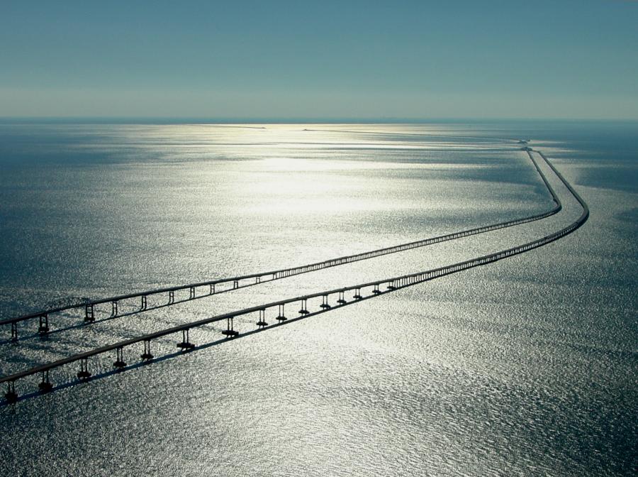
The bridge-tunnel — virtually in the open sea with the Atlantic Ocean on one side and the Chesapeake Bay on the other — is an engineering marvel. Twenty mi. long between its toll plazas, it is the largest bridge-tunnel complex in the world, combining 12 mi. (19.3 km) of trestle, two 1-mi. (1.6 km) tunnels, two bridges, approximately 2 mi. (3.2 km) of causeway, four man-made islands, and 5.5 mi. (8.8 km) of approach roads.
“I ride across it so often that I don’t realize its impact,” said Tom Anderson, director of finance and deputy director of the Chesapeake Bay Bridge and Tunnel District at its headquarters in Cape Charles, Va. “But when I occasionally cross with people who haven’t done it before, they are just blown away by it. When you’re out there crossing the mouth of Chesapeake Bay and you can’t see land, it’s amazing, very beautiful, and safe.”
It’s just motorists, water, sky and wind on this route allowing them to experience the surging ocean, the beauty of the bay, and the soaring grace of a construction feat that has become one of America’s icons, enjoyed by more than 93 million people over the past 42 years. In 2005, more than 3.6-million vehicles used the crossing.
Filled a Big Need
Planning for the bridge-tunnel goes back to the 1950s. Highway planners realized that the mouth of the Chesapeake was the last obstacle to uninterrupted travel along the Eastern Seaboard.
Cars crossed on ferries, which took 85 minutes (in good weather) to cross between Virginia’s Eastern Shore (Kiptopeke/Cape Charles) and the Norfolk/Virginia Beach area. The flagship of the seven-ship fleet, the 367-ft. SS Pocahontas, could carry 1,200 passengers (who often got seasick in storms) and 120 vehicles. The six other ferries carried from 68 to 120 cars and up to 1,200 people. The ships stopped running at 1 a.m.
The bridge-tunnel, which replaced the ferries, saves approximately 95 mi. compared with taking Interstate 95 (I-95) on a north-south trip between New York and Virginia Beach/Norfolk.
“Wilmington, Delaware, is the decision point when traveling south,” said Paige Addison, marketing specialist of the District.
She added that the bridge-tunnel also has been a great boon to people like herself who live in the area.
“I cross it quite often to go to the doctor, shop, attend the theater in Virginia Beach or Norfolk and even vacation with my family,” she said. “Since I live on the eastern shore, I am accustomed to the bridge-tunnel being the route for me to travel. However, no two trips are ever the same — from beautiful sunrises and sunsets, to dolphins jumping in the water or ships passing through one of the channels, each drive out to sea is a spectacular one.”
A Novel Challenge
The bridge-tunnel, part of U.S. 13, was a unique challenge. Following its opening in April 1964, it was selected as one of the “Seven Engineering Wonders of the Modern World” and in 1965, in competition with more than 100 other projects, it received the “Outstanding Civil Engineering Achievement” award from the American Society of Civil Engineers (ASCE). Additionally, it was recognized in 2000 by Structural Engineer Magazine as “one of the seven engineering wonders of America for the 20th Century.”
“Every part of the job was a big challenge because at that time nobody had built a facility like this,” said Robert E. Johnson, director of maintenance for the bridge-tunnel. “This is the longest bridge-tunnel combination in the world. There are other long bridges like the one over Lake Pontchartrain, but that’s over an inland area and it’s not very high. There are long tunnels, but they don’t usually have any kind of bridge attached to them. What makes our facility so unusual is having all these items joined together.
“The bridge-tunnel also had to be built very substantially. Hurricanes tend to hit us pretty hard. Large Nor’easters come through and can beat you up a lot with water. It’s one of the things about being between ocean and bay. You just compensate for it.”
(Although the structure is very strong, the bridge-tunnel is closed if winds reach hurricane force, and restricted for some types of vehicles at certain other wind speeds because the vehicles themselves could be unstable.)
Extensive Studies
After the Virginia General Assembly authorized the Chesapeake Bay Ferry Commission to explore construction of a fixed crossing in 1956, three portable drill towers performed test borings into the sand bottom at the mouth of the bay beginning in 1957. The bottom was mostly sand, with solid rock only at depths of 2,000 ft. or more. They also charted water currents precisely.
Results showed a crossing was feasible. In the summer of 1960, the Ferry Commission sold $200 million in revenue bonds to private investors, with funds from future tolls pledged to pay principal and interest.
A construction contract was awarded to the joint venture of Tidewater Construction Corp., Merritt Chapman & Scott, Raymond International, and Peter Kiewitt & Sons Inc. No local, state or federal tax money was used in the project.
The route was laid out from nine survey towers.
Construction of a two-lane bridge-tunnel began in October 1960 and was completed in April 1964, serving both northbound and southbound traffic.
The bridge-tunnel was officially named the Lucius J. Kellam Jr. Bridge-Tunnel in 1987, honoring the man who spearheaded the project as a member of the bridge-tunnel commission from 1954 until his death in 1995.
By 1989, studies concluded that parallel bridges, trestles and roadways would be needed to meet future traffic demands and provide a safer crossing. In May 1995, the Chesapeake Bay Bridge and Tunnel Commission awarded a $197 million construction contract for the parallel span to a joint venture of PCL Civil Constructors Inc., Denver, Colo.; The Hardaway Co., Columbus, Ga.; and Interbeton Inc., Rockland, Mass. This project, which cost $250 million, was financed by funds from the bridge and tunnel district and through the sale of additional revenue bonds.
A second parallel two-lane crossing, 250 ft. to the west, began in the summer of 1995 and was completed in April 1999. Dedicated to southbound traffic only, it includes parallel bridges, trestles and roadways. The first roadway is 28 ft. wide and the second 36 ft. wide.
Illustrating the magnitude of the job, the two projects used 34,000 railroad-carloads of rock, 4 million cu. yds. (3 million cu m) of sand, 110 million lbs. (50 million kg) of steel, 56 mi. (90 km) of aluminum railing (or 168 mi. [270.4 km] of tubing), approximately 550,000 cu. yds. (420,505 cu m) of concrete, and nearly 5.5 million ceramic tiles (in the tunnels).
The second project did not include expanding the four islands or additional tunnels. New tunnels are expected to be constructed in the future.
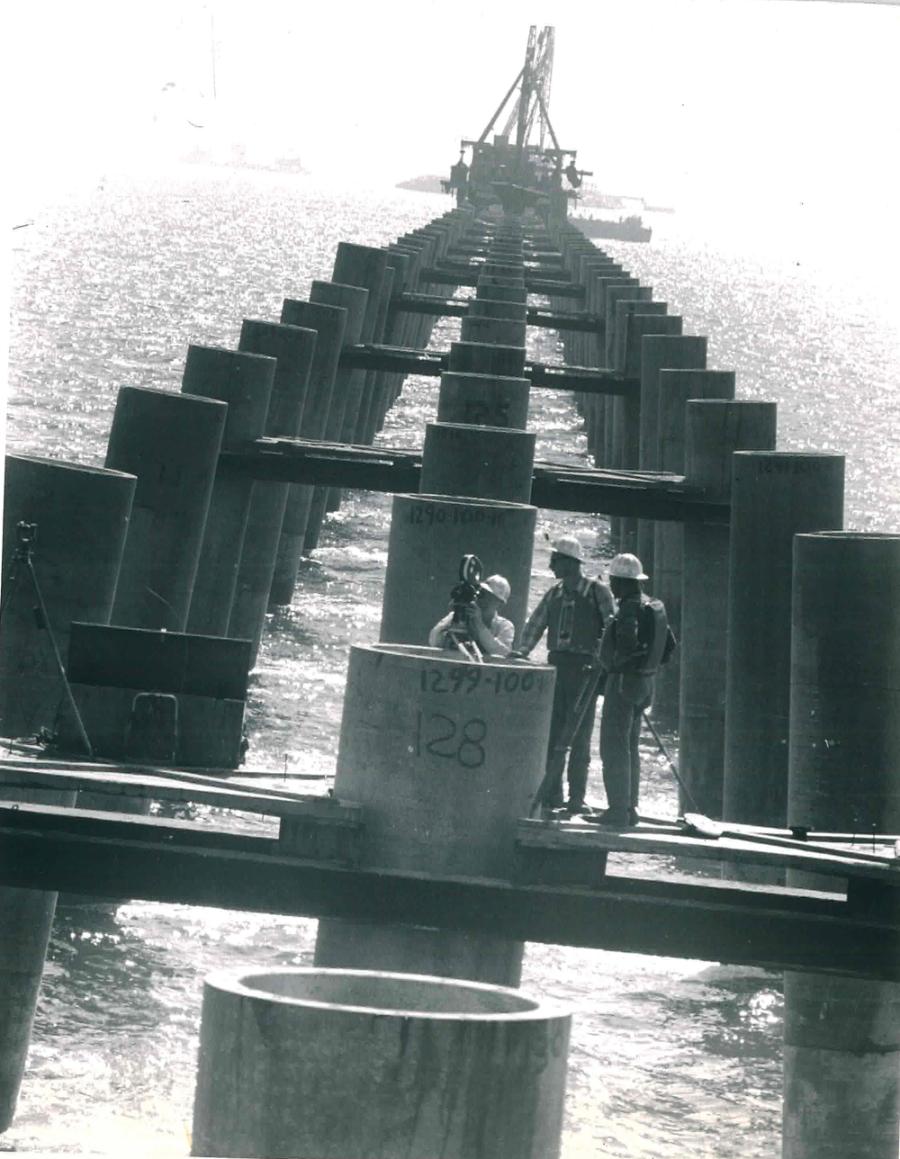
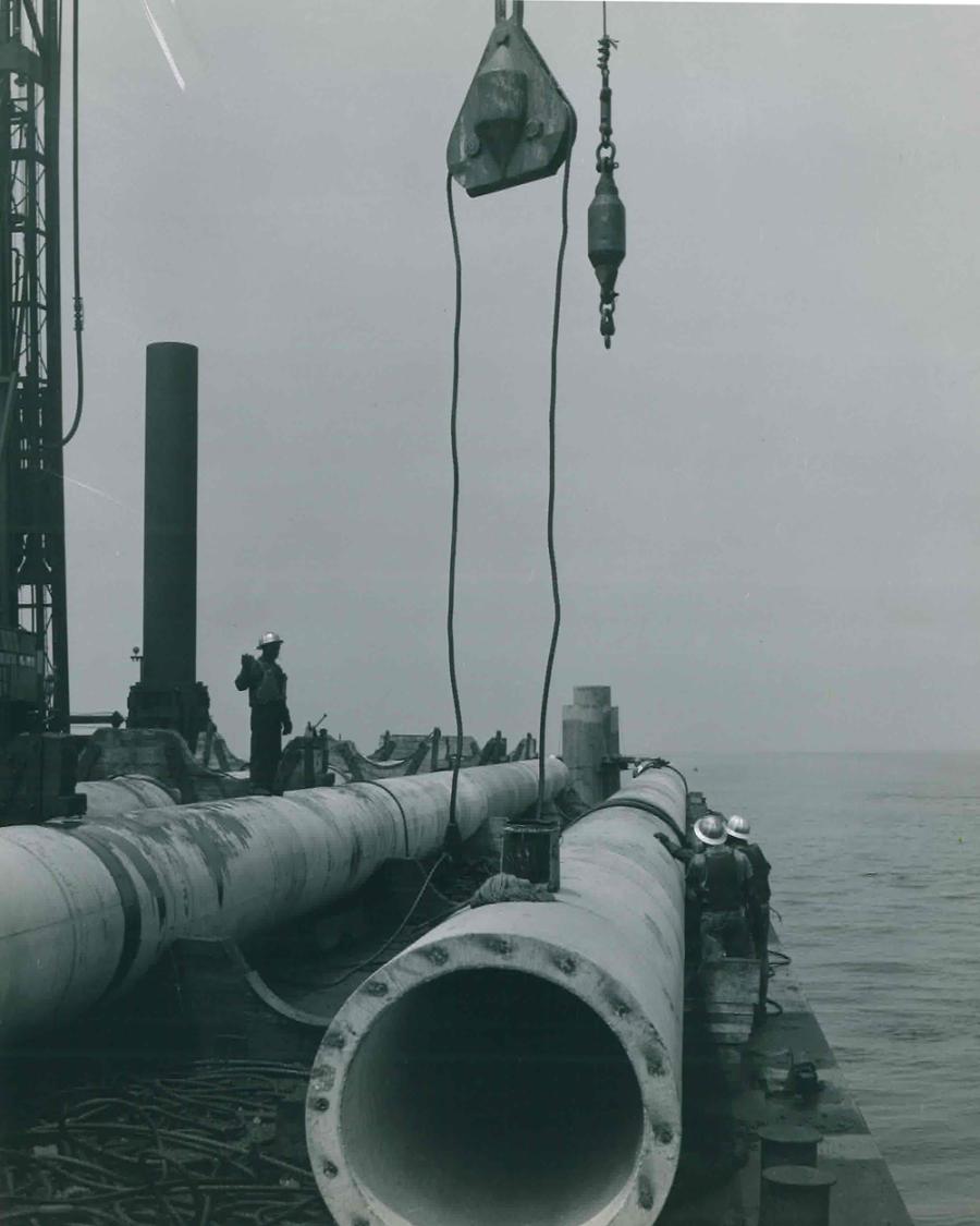
Pilings in the Sea
The major portion (12.2 mi. [19.6 km]) of the bridge-tunnel was designed as a low-level (30 ft. above water) trestle over relatively shallow water 30 to 40 ft. deep. This structure accommodates small boats and keeps the road above the waves. Like everything else on the bridge-tunnel, its construction involved much originality and engineering expertise.
Trestle components were fabricated on an assembly-line basis at an 80-acre pre-stressed concrete construction yard at Bayshore Concrete Products in Cape Charles.
Concrete was fed into forms at the yard to make hollow pilings 54 in. (137.2 cm) in diameter, from 80 to 172 ft. (24.2 to 52.4 m) long, and with walls 5 in. (12.7 cm) thick. Barged out on the water, and lifted by crane, the pile sections were driven into the bottom of the bay from a DeLong-type barge, nicknamed the “Big D.”
First, high-pressure water nozzles prepared a path for the piling. A steam-driven pile driver then hammered in the piling. The pile driver could be raised or lowered in the seabed by 500-ton (453 t) capacity hydraulic jacks.
A total of 2,580 pilings were driven down for the first crossing, and 2,591 for the second.
On the original crossing, sand was dumped into each piling to make it more secure.
On the initial crossing, the piles were driven “to refusal” (until they wouldn’t go down any further). On the second, electrodes attached to each piling told how far to go to a required bearing.
Building the Roadbed
How does one build a secure, stable roadbed on pilings in the sea?
Close attention to engineering fundamentals produced a trestle structure that has withstood time, storms and traffic.
“We put a steel cage inside each group of three pilings and poured in concrete to form a base for a 4-foot by 4-foot concrete cap, which joined the pilings together,” said Johnson. “The caps were placed from a traveling bridge 175 ft. long with a stiff-leg derrick at each end. This piece of equipment was known as the ’Two-Headed Monster.’ On top of each cap, we placed four sections of concrete roadbed in the first crossing and three sections in the second crossing. These concrete slabs were pre-stressed at Bayshore for the first crossing while work for the second crossing was done at Little Creek, Virginia.
“We placed a stressing jack on one side of the bridge, ran stress wires through ducts in the slabs, and pulled them together. They were joined as one solid mass, which was pre-stressed and post-tensioned. All of that was grouted and encased in concrete so it wouldn’t slip back apart. Later in the project, we put asphalt on top of that.”
The resultant concrete-span sections were 75 ft. (22.8 m) long on the first structure and 100 ft. (30.5 m) long on the second.
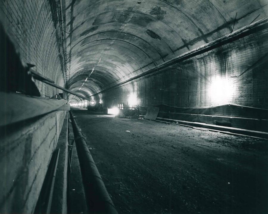
How Do You Sink a Tunnel?
The two tunnels (both two-lane), which are used by both the 1964 and 1999 crossings, are another example of what makes the bridge-tunnel such a great accomplishment.
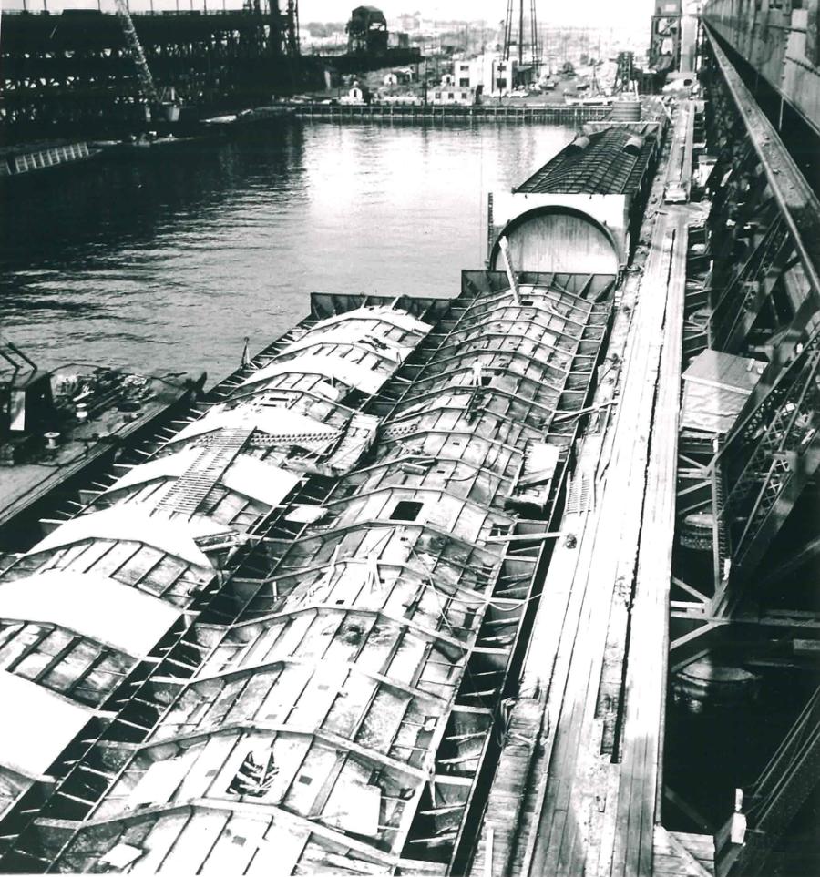
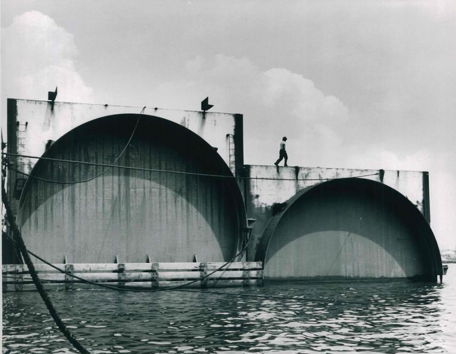
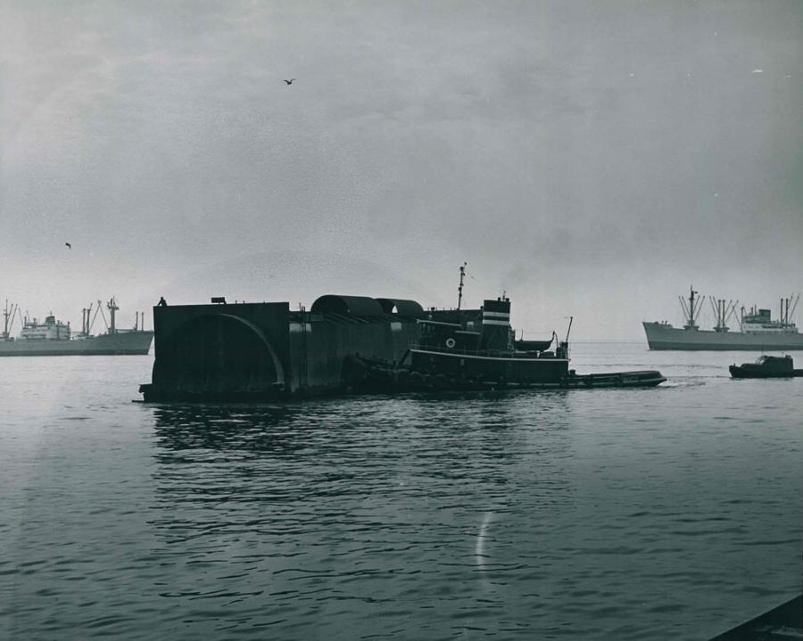
The tunnel structure consists of tube sections 37 ft. (11.3 m) in diameter and 300 ft. (91.4 m) long, made of prefabricated composite structural steel and reinforced concrete. Fabricated at Orange, Texas, they were towed approximately 1,700 mi. (2,735.9 km) to Norfolk (Sewell’s Point), where they were sealed as a preparation for being sunk into trenches which dredges had scooped out under two of the world’s busiest military and commercial shipping channels, which were originally 45 ft. deep.
“Each tube was built like a boat, like a big-old barge floating,” said Johnson. “They put concrete between two steel shells. As they added concrete and did concrete work inside, it gave more and more weight to the tube section. They put just enough concrete so they had just enough buoyancy to keep from sinking. At that point, they would float the section out to the channel where they were going to install that section.
“They would line up the section [over the tunnel area] using two railroad barges joined together, which actually held the section. Then they would start filling the tube with more concrete until it reached negative buoyancy and started sinking, being lowered by winch. The barges held concrete mixers.
“Deep-sea divers on each side of the tube helped guide it into position for connecting it with the previous tube. An ’I’ on the new section would lock with a hook on the previous section. As they rested on the bottom, the two sections were joined, and welders would weld the joint all around the outside. After Tremie concrete was placed over the joint, welders went inside to cut the bulkheads out.”
A total of 37 tube sections were thus joined for the two tunnels — the Thimble Shoal Tunnel, which is 5,734 ft. (1,748 m) long, and the Chesapeake Channel Tunnel, which is 5,423 ft. (1,653 m) long.
After the tubes were joined, sand backfill was placed along the sides and to a minimum depth of 10 ft. over the top to ensure permanent stability. A layer of armor rock was placed on top of the sand in some areas to protect against anchors.
Total deviation on the entire bridge-tunnel is less than one-half in. (1.3 cm) — and this without benefit of the Global Positioning System (GPS) on the initial span, which used the nine survey towers to assure this accuracy. However, GPS was a “luxury” used for exact alignment during the construction of the parallel crossing in the 1990s.
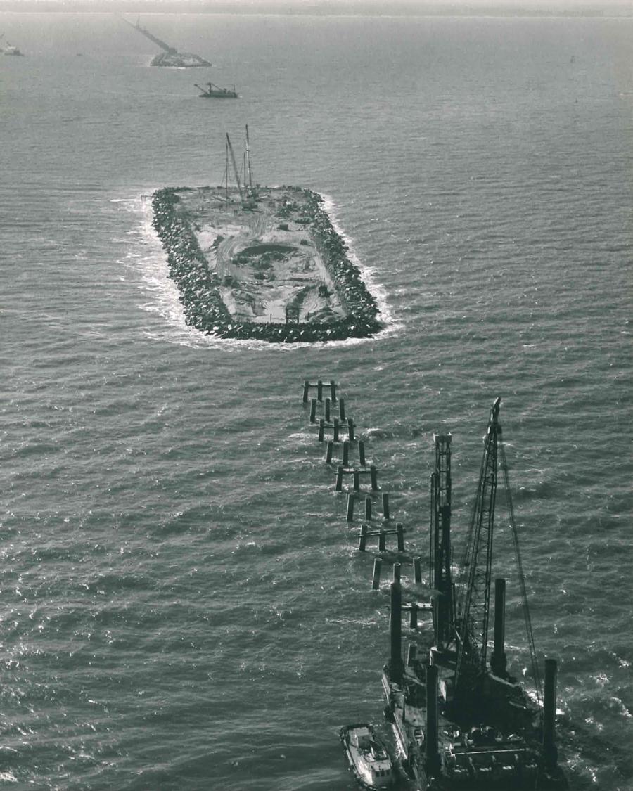
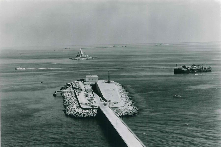
Man-Made Islands
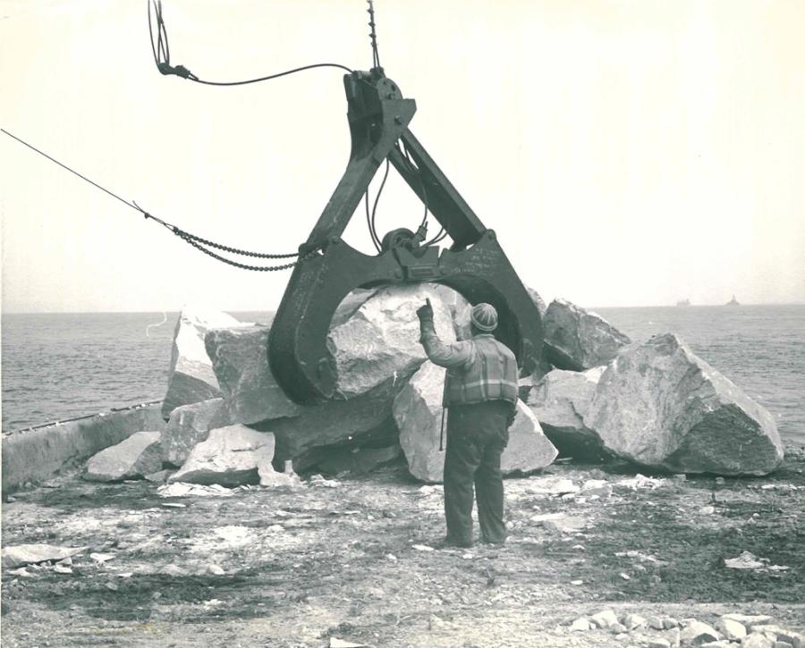
Each of the tunnels is anchored on man-made islands, which were built in 35 to 45 ft. of water, providing a transition from the trestle roadway to the tunnel tubes. Each of the four islands is approximately 1,500 ft. (457 m) long and 230 ft. (70 m) wide at the top (approximately the size of Yankee Stadium) and approximately 30 ft. (9.1 m) above mean water level. Thousands of car-sized boulders, known as armor rock, were dropped to create the outer rims of the islands and were then filled with approximately 2 million lbs. of sand and rock.
Approximately 1.2 million tons (1.1 million t) of rock, much of it brought by railroad car from Western Virginia, protects the islands from erosion and high water.
Island No. 1, the first island from Virginia Beach, includes a 625-ft. fishing pier, a seaside restaurant, and gift shop. It’s a great stop on the ride over — and a refuge if one needs a respite from rain.
The contractor for the islands was Merritt, Chapman and Scott.
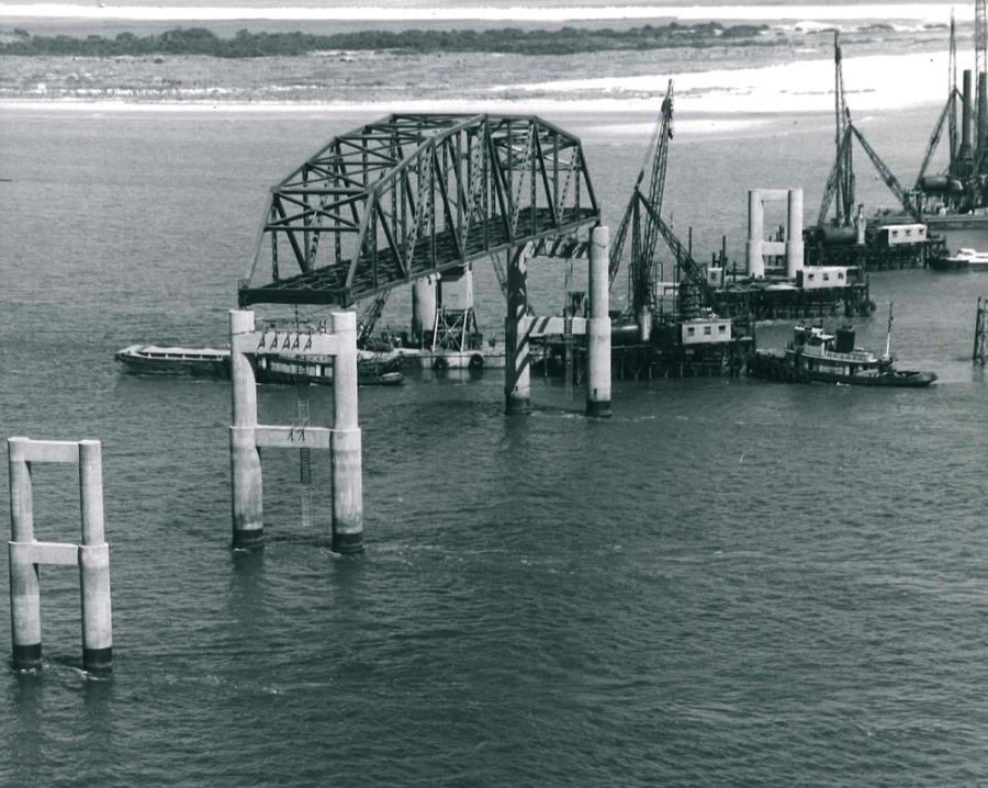
Using the Tide in Building Bridges
Another amazing engineering feat — crews used the tides to put the first North Channel Bridge in place.
American Bridge Co. constructed the bridge deck and steel-frame superstructure at Cape Charles. This structure was then floated out on barges to be above the bridge foundation bearings.
“It was barged in on flood tide when the tide was high,” Johnson said. “Then, when the tide began to go out, we pumped water into the barge to sink it away from the structure. Once the barge was below the structure, we just pulled it out from under, leaving the bridge in place.”
The bridge, now used for northbound traffic, is 3,798 ft. (1,158 m) long, with a vertical clearance of 75 ft. (22.9 m) and horizontal clearance of 300 ft. (91.4 m).
The new North Channel Bridge for southbound traffic is 3,100 ft. (944.9 m) long with the same clearances.
The bridge-tunnel also includes two bridges over Fisherman Inlet, 460 ft. (140.2 m) and 458 ft. (139.6 m) long, with 40 ft. (12.2 m) vertical and 110 ft. (33.5 m) horizontal clearance.
Priority Is Safety
Exposed to the elements of Mother Nature, the bridge-tunnel needs to be meticulously maintained.
“We have a contingent of about 64 people in our Maintenance Department,” Johnson said. “Besides various phases of electrical and mechanical maintenance, we have people in traffic control and underbridge inspection, plus vehicles to repair concrete; if there is any kind of spall or crack, we will go down and do repairs.
“You might compare it to a city. We take care of everything from water to sewers, trucks running up and down the bridge, potholes, and painting. We usually spot-paint every three to five years. The actual paint system on the bridge was warranted for 10 years, but we return periodically and touch that up.”
The symbol of the Chesapeake Bay Bridge-Tunnel, a white seagull in flight against a blue background, captures the spirit of this construction accomplishment. Incidentally, the toll is $12 each way for passenger vehicles with a $5 discount if one returns within 24 hours.
For more information on the bridge-tunnel, visit www.cbbt.com.CEG


