Our Main Office
Construction Equipment Guide
470 Maryland Drive
Fort Washington, PA 19034
800-523-2200
Fri July 12, 2013 - West Edition
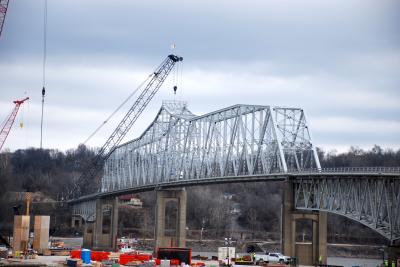
During the 1989 Loma Prieta earthquake, a 50-ft. (15 m) section of the upper deck on the eastern span of the San Francisco-Oakland Bay Bridge east of Yerba Buena Island collapsed. An interim retrofit was performed to shore up the bridge while the state government made the decision whether to do a complete retrofit or build a new bridge.
Analysis determined that the damage could have been much worse, in part because of poor soil conditions under the eastern end of the bridge. Because the bridge sits between two fault lines — the San Andreas and the Hayward — and is vulnerable to a major event, and because the Army Corps of Engineers warned that a retrofit would require extensive ongoing maintenance, it was determined to build an all-new bridge north of the original structure.
Earth-Shaking Design
Several alternatives were considered, but the Engineering and Design Advisory Panel of the Metropolitan Transportation Commission ultimately chose a design by Caltrans and T.Y. Lin International.
The rising cost of materials — particularly steel and concrete — contributed to the high price tag. “Upward revisions in the early days of planning contributed to raising the cost,” said John Goodwin, public information officer with the Metropolitan Transportation Commission in Oakland. Insurance costs became increasingly pricey as well. In addition, because the primary structure of the signature self-anchored span cannot be self-supporting until complete, it required the building of a temporary bridge to support the final span, adding to costs.
The project, which is the largest public works project in California to date, has a forecast budget of $6.4 billion. The primary source of funding is tolls on state-owned toll bridges in the Bay area, with 60 percent of funds coming from tolls, 5 percent ($323 million) from federal funds and the rest from state funds. “The onus is on tolls,” Goodwin said, noting that California implemented a toll increase in 1998 and again in 2007.
The new east span will feature a pair of side-by-side, five-lane concrete viaducts that connect to a single-towered, self-anchored suspension span. A transition structure links the SAS to the existing double-deck tunnel.
“The tunnel has no additional capacity,” Goodwin said, “so we can’t create a bigger bridge.” However, full-size shoulders will be added on each side, as well as a bike/pedestrian path — and when completed, it will be the largest bridge of this type.
The project is so big it is divided into 16 major contracts and four major sections: the Yerba Buena Island Transition Structure (YBITS), the all-steel self-anchored suspension (SAS bridge), the Skyway and the Oakland Touchdown. Prime contractor on the SAS project is ABF, a joint venture between Pennsylvania-based American Bridge Co. and Fluor Corporation of Irving, Texas.
Innovative energy-absorbing techniques were incorporated for state-of-the-art safety, according to Goodwin. The steel and concrete replacement span is engineered to withstand ground motion forecasts over a 1500-year period and is expected to last at least 150 years with proper maintenance. Designed to absorb energy, sections move independently with critical components designed to deform so they can be removed and replaced if necessary. Due to 20 hinge pipe beams and sacrificial tubular end keys, the flexible structure should be able to survive a Maximum creditable earthquake, estimated at 8.5 moment magnitude.
The tower consists of four columns joined horizontally by sacrificial box structures, known as shear link beams, designed to absorb earthquake-induced motion that will allow the tower to sway without incident.
To build the tower, columns were lifted and bolted into place before being topped with a cap that carries the cable saddle. After being floated in from China, the columns were lifted onto a temporary scaffold for placement. A second set of columns was erected by a gantry on top of the scaffold and placed over the first four columns, to which they were bolted. An even larger crane lifted this set into place over the previous set. The final set of columns was set in 2011, extending the height of the tower to 480 ft. (146 m). Once the cable saddle was placed, the tower was complete, at a final height of 525 ft. (160 m).
Spanning The Bay
Moving east to west from Oakland to San Francisco, the bridge begins with the Oakland Touchdown, an elevated road that leads from the shore to the skyway, curving to align with the existing ground-level approach road.
Next is the longest section of the new bridge, the 1.2-mi. (1.9 km) Skyway. Sweeping parallel decks arc out over the bay, providing both a stunning view and a graceful image. It is composed of 452 pre-cast concrete segments that stand three stories high, 90 ft. (27 m) wide and 25 ft. (6.6 m) long.
The deck surface is paved with durable, weather-resistant high-strength polyester concrete fabricated in Stockton and transported by barge. The largest segments of their kind ever cast, they were lifted into place by custom-made winches. Similarly, two of the heaviest lifts in California history placed the two 2,000-ton (1,814 t) steel transition segments on the western end. These segments will connect the Skyway with the SAS.
Fourteen sets of piers ranging in height from 45 to 115 ft. (14 to 35 m) support the Skyway sections. They were constructed of 160 rebar and concrete-filled steel piles 8.5 ft. (2.6 m) in diameter. The piles were welded into pile caps underneath the columns and were driven as deep as 300 ft. (91 m) to anchor in stable soils. Prime contractor Kiewit/FCI/Manson — a joint venture — completed construction in 2008.
The main SAS span is not only unusual for being rarely built, but also unique because of its single tower and asymmetrical design. A two-tower cable-stayed design would require deep footings in bedrock and a conventional two-tower suspension bridge would require a massive anchor to be built in deep bay mud.
The tower east of the island is on bedrock, Goodwin said. However, because the soil conditions under the eastern end of the bridge prohibit setting the Skyway pilings in bedrock, they are set in the firm archaic mud found below the soft muds deposited by distant placer mining in the late 19th century. Large-diameter tubular piles were driven inside cofferdams at angles to form a splayed footing. Next, a reinforced concrete pad was poured at the bottom of the cofferdam to create a footing for the column.
Anchored into the bridge superstructure on the east side of the SAS, the single cable rises to the tower and then descends to wrap around the west side of the SAS before climbing to the top of the tower again and then descending back to the east anchorage to form the main cable. The shorter western side of the SAS is pulled down against the forces imposed by the longer eastern span. To avoid uplift in the supporting columns, the span is terminated with a massive concrete end weight that carries the turning saddles for the main cables.
The unique design of the SAS posed a lot of challenges and introduced a lot of expense, Goodwin said. The tower and orthotropic box girders were fabricated by ZPMC in Shanghai and shipped in. To lift them into place required deployment of a specially built shear-leg barge — the largest of its kind on the west coast. The Left Coast Lifter is a giant barge crane that was used to place the 28 main deck box structures. Building, outfitting and transporting it added about $50 million to the project costs, Goodwin said.
The western-most section of the new east span is the 1,542-ft. (470 m)-long Yerba Buena Island Transition Structure, which links the SAS with the island. MCM Construction is the prime on this section.
Timeline
Construction to replace the eastern span of the bridge began in 2002. Because of the way the bridge ties in to the tunnel on the island with a curved double-deck truss causeway, temporary bridge structures were erected in 2009.
The targeted completion date is Sept. 3, 2013, but Goodwin said there is uncertainty about it. “The engineering challenges have been met and the load transfer is complete, but in March we encountered a problem with high-strength steel anchoring rod.”
The steel anchoring rods that secure the seismic safety components had been in place since 2008, but not tensioned because the 9 to 17 ft. long (2.7 to 5.2 m) bolts under the bridge deck couldn’t be tightened until the load was transferred from the temporary supports to the cable system. When it was, one third of the 96 anchor rods that secure the sheer keys failed. “An investigation indicates the failure is due to hydrogen embrittlement,” Goodwin said. “The steel proved to be too hard, but not tough enough.”
He said that galvanizing the rods to prevent rust may have contributed to the problem. Tests on 192 similar rods used to secure other shear keys and seismic bearings have different results. Although made of the same grade of steel, the rods manufactured in 2010 are of a more consistent material.
“We must engineer and fabricate a substitute to retrofit the system for securing shear keys to 1 and 2 to the pier cap,” Goodwin continued. Because they can’t be removed, new steel saddle systems with the same clamping power will have to be added — at a cost of up to $10 million. “Another concern is stress corrosion cracking and the Toll Bridge Program Oversight Committee is now investigating the long-term integrity of more than 2,000 high-strength steel fasteners used at 17 different locations on the SAS project.”
It’s simply the most recent challenge that has plagued this project. Although weather hasn’t caused any delays, there have been plenty due to design, politics and cost over-runs. A two-year delay and several hundred millions of dollars in additional costs was attributed to an alignment controversy that led the U.S. Navy to restrict access to the soil engineers.
In 2005 the FBI investigated charges by former welders and inspectors regarding allegations of defective welds, many of which were embedded in concrete underwater. Tests by three independent contractors indicated that the welds either met or exceeded specifications.
In November 2011 there was concern about the potential of falsified inspection reports, particularly in regards to foundation testing practices. A report from a panel of independent experts in March 2012 confirmed the integrity of the tower foundation.
Challenge Accepted
Welding was difficult. “The superstructure is composed of 28 separate orthotropic box girders (14 in each direction),” Goodwin explained. “Those at the eastern end contain the anchoring system contain 137 separate cable strands.”
Workmanship was a challenge complicated by difficult access, which subsequently added to the cost and the timeline. “Minimizing disruption was a huge challenge when you’re working on a bridge that sees 250,000 vehicles a day,” Goodwin said.
Total closures were kept to a minimum: Labor Day 2007 and 2009 to move out sections of the old bridge and President’s Day 2012 to realign the eastern end of the original 1936 east span. The final closure will occur just prior to opening to reconfigure.
Material challenges were also plentiful, and material used on the project was abundant.
• Oakland Touchdown: 11,600 tons (10,523 t) of reinforcing steel; 1.5 million cu. ft. (42,475 cu m) of concrete
• Skyway: 120 million lbs. (54 million kg) of reinforcing steel; 200 million lbs. (90 million) of structural steel; 200,000 linear ft. (60,960 m) of steel piling; 450,000 cu. yds. (34,405 cu m) of concrete
• SAS: 35,200 tons (31,932 t) of steel (temporary supports required 20,000 tons [ 18,143 t] of steel)
• YBITS: 7,600 tons (6,894 t) of steel; 31,307 cu. yds. (23,936 cu m) of concrete
Hoping that the construction challenges will soon be behind them, Goodwin looks forward to an on-target completion. The SAS tower was completed in 2011 and the entire SAS superstructure was finished by summer 2012. Load transfer was completed on Nov. 20, 2012, officially making the 2,047-ft. (624 m) span the largest self-anchored suspension bridge in the world.
The entire roadway of the bridge is now largely complete. The bridge is now self-supporting so temporary scaffolding is being removed. All that’s left is paving, painting, a lot of punch-list items and resolution of the problems with the high-strength steel rods.
Construction Equipment Guide
470 Maryland Drive
Fort Washington, PA 19034
800-523-2200
Construction Equipment Guide covers the nation with its four regional newspapers, offering construction and industry news and information along with new and used construction equipment for sale from dealers in your area. Now we extend those services and information to the internet. Making it as easy as possible to find the news and equipment that you need and want.
Contents Copyrighted 2024, by Construction Equipment Guide, which is a Registered Trademark, registered in the U.S. Patent Office. Registration number 0957323. All rights reserved, nothing may be reprinted or reproduced (including framing) in whole or part without written permission from the publisher. All editorial material, photographs, drawings, letters, and other material will be treated as unconditionally assigned for publication and copyright purposes and are subject to Construction Equipment Guide’s unrestricted right to edit and comment editorially. Contributor articles do not necessarily reflect the policy or opinions of this publication.
Read our privacy policy here.
Mastodon