

Our Main Office
Construction Equipment Guide
470 Maryland Drive
Fort Washington, PA 19034
800-523-2200
Wed September 26, 2012 - Northeast Edition
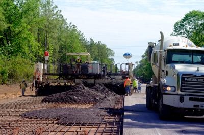
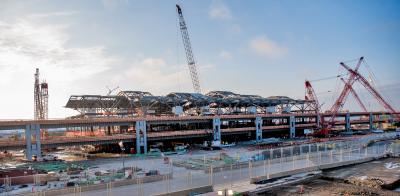
Dominion Transmission, the natural gas transportation subsidiary of Dominion Resources, recently placed its Appalachian Gateway Project into service on time and within budget following two years of construction. The project will reportedly allow the transport of 484,260 dekatherms per day in firm transportation of natural gas produced in West Virginia and southwest Pennsylvania to storage fields and pipelines in Pennsylvania.
“The Appalachian Gateway Project will transport natural gas produced in West Virginia and southwest Pennsylvania to where it can be sold to customers in the Northeast and Mid-Atlantic,” said Thomas F. Farrell II, chairman, president and chief executive officer of Dominion Resources. “Combined with our Gathering Enhancement Project, Dominion invested more than three-quarters of a billion dollars to increase the flow of natural gas in the area. This should greatly benefit the regional economy.”
For the Appalachian Gateway Project, Dominion constructed four new natural gas compressor stations and upgraded two existing compressor stations, adding about 17,800 hp to the Dominion system. Approximately 110 mi. (177 km) of new pipeline was constructed, beginning in West Virginia and terminating at Dominion’s and Spectra’s jointly owned Oakford facility in Delmont, Pa., east of Pittsburgh.
Dominion Transmission is one of the nation’s largest producers and transporters of energy, with a portfolio of approximately 28,000 megawatts of generation, 11,000 mi. (17,703 km) of natural gas transmission, gathering and storage pipeline and 6,300 mi. (10,139 km) of electric transmission lines. Dominion operates the nation’s largest natural gas storage system with 947 billion cu. ft. of storage capacity and serves retail energy customers in 15 states.
The project was approved by the Federal Energy Regulatory Commission on June 16, 2011. The reported cost was approximately $600 million.
According to the project’s Web site, construction of the pipeline was set up like a moving assembly line. The pipeline was broken into manageable lengths, called construction spreads, which varied from 50 to 60 mi. (80.5 to 96.5 km) in length. Each spread was handled by various crews with different responsibilities. As one crew completed its work, the next crew moved into position to complete its piece of the construction process.
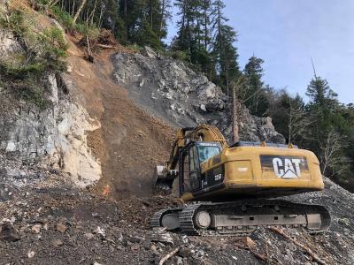
Clearing and Grading
The clearing and grading crew led the construction spread and was responsible for removing trees, boulders and debris from the construction right-of-way and preparing a level working surface for heavy construction equipment.
The crew installed silt fences along edges of streams and wetlands to prevent erosion of disturbed soil. Trees inside the right-of-way were cut down and removed or stacked along the side of the right-of-way. Brush was shredded or burned, and topsoil was sometimes stripped to a predetermined depth and stockpiled along the sides of the right-of-way.
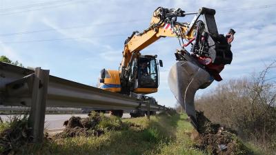
Trenching
The trenching crew used wheel trenchers and backhoes to dig the pipe trench.
The U.S. Department of Transportation requires the top of the pipe to be buried a minimum of 30 in. (76.3 cm) below the ground surface in rural areas, so the depth of the trench was at least 5 to 6 ft. (1.5 to 1.8 m) deep for pipe 30 to 36 in. (76.2 to 91.4 cm) in diameter.
For less rural areas, the requirement was for the pipe to be buried a minimum of 36 in. However, it was buried deeper at stream and road crossings.
If the crew found large quantities of solid rock during the trenching operation, special equipment and/or explosives were used to remove the rock.
Pipe Bending
The pipe bending crew used a bending machine to make slight bends in the pipe to account for changes in the pipeline route and to conform to the topography. The bending machine used a series of clamps and hydraulic pressure to make a smooth, controlled bend.
Coating
Line pipe is externally coated to inhibit corrosion by preventing moisture from coming into direct contact with the steel. Normally, this is done at the mill where the pipe is manufactured or at another coating facility location before it is delivered to the construction site.
All coated pipe, however, has uncoated areas 3 to 6 in. from each end to prevent the coating from interfering with the welding process. Once the welds were made, a coating crew coated the field joint before the pipeline was lowered into the ditch.
Pipeline companies use several different types of coatings for field joints, the most common being fusion bond epoxy or polyethylene heat-shrink sleeves. Prior to application, the coating crew thoroughly cleaned the bare pipe with a power wire brush or sandblast to remove any dirt, mill scale or debris. The crew then applied the coating and allowed it to dry prior to lowering the pipe in the ditch.
Before the pipe was lowered into the trench, the coating of the entire pipeline was inspected to ensure it was free of any defects.
Lowering In
Lowering the welded pipe into the trench was accomplished using a series of side-booms to lower the welded sections into the trench. Non-metallic slings protected the pipe and coating as it was lifted and moved into position.
In rocky areas, the contractor sometimes placed sandbags or foam blocks at the bottom of the trench prior to lowering-in to protect the pipe and coating from damage.
Backfilling
Once the pipe was placed in the trench, the trench was backfilled using a backhoe or padding machine, depending on the soil makeup.
The soil was returned to the trench in reverse order, with the subsoil replaced first, followed by the topsoil. This ensured that the topsoil was returned to its original position. In areas where the ground was rocky and coarse, crews screened the backfill material to remove rocks. Sometimes, clean fill was brought in to cover the pipe, or the pipe was covered with a material to protect it from sharp rocks. Once the pipe was sufficiently covered, the coarser soil and rock could be used to complete the backfill.
Open Cut River and Stream Crossings
This crossing method involved excavating a trench across the bottom of the river or stream to be crossed with the pipeline. Depending on the depth of the water, the construction equipment was placed on barges or other floating platforms to excavate the pipe trench. If the water was shallow enough, the contractor could divert the water flow with dams and flume pipe to allow backhoes, working from the banks or the streambed, to dig the trench.
The contractor prepared the pipe for the crossing by stringing it out on one side of the stream or river and then welding, coating and hydrostatically testing the entire pipe segment. In some cases, sidebooms carried the pipe segment into the stream bed, similar to construction on land. Other situations called for the construction crew to float the pipe into the river with flotation devices and position it for burial in the trench. Concrete weights or concrete coating ensured the pipe would stay in position at the bottom of the trench once the contractor removed the flotation devices.
Directional Drilling
Another crossing method that was used was directional drilling. While not always feasible, this method allowed contractors to avoid the excavation of a trench across the bottom of the crossing. It is a method considered for longer crossings, and requires special geological conditions at the crossing location. Basically, it involves drilling a hole large enough for the pipeline to be pulled through it and in the shape established by the designers.
Before a directional drill could be designed, core samples had to be taken on both sides of the crossing to evaluate the underground rock and sand formations. If the subsurface would support a directional drill, the engineer could design a crossing that established the entry point, the exit point of the pipeline crossing, and its profile as it would traverse under the crossing.
While this drilling was in progress, the line pipe sections were strung out on the far side of the crossing, opposite of the drilling, to be welded. Once welded, the joints were X-rayed, coated, hydrostatically tested, and then placed on rollers in preparation for being pulled back through the drilled hole.
Once the drilling operation was complete, the cutting head was removed and the drill string attached to the welded pipeline segment. The crew used the drilling rig to pull the pipeline segment back through the drilled hole, where it was then connected into the pipeline on both ends.
Wetlands
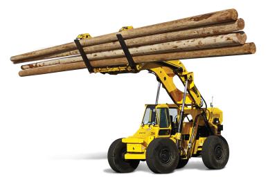
“Pipelining” in wetlands or marshes sometimes requires another special construction technique. In some situations, crews placed large timber mats ahead of the construction equipment to provide a stable working platform. The timber mats act much like snowshoes, spreading the weight of the construction equipment over a broad area. The mats make it possible to operate the heavy equipment on the unstable soils.
Stringing
At steel rolling mills where the pipe was fabricated, it was inspected to assure that it met industry and federal government safety standards. For corrosion control, the outside surface was treated with a protective coating.
The pipe was then transported from the pipe mill to a pipe storage yard in the vicinity of the project location. The pipe lengths typically were 40 to 80 feet long. A stringing crew used specialized trailers to move the pipe from the storage yard to the pipeline right-of-way.
Next, the crew carefully distributed the various pipe joints according to the design plan since the type of coating and wall thickness can vary based on soil conditions and location.
For example, concrete coating may be used under streams and wetlands, and heavier wall pipe is required at road crossings and in special construction areas.
Welding
The pipe gang and a welding crew were responsible for welding, the process that joins the various sections of pipe together into one continuous length.
The pipe gang used side booms to pick up each joint of pipe, align it with the previous joint, and make the first pass of the weld. The pipe gang then moved down the line to the next section, repeating the process. The welding crew followed the pipe gang to complete each weld.
Hydrostatic Test
According to the company’s Web site, before the pipeline was put into natural gas service, the entire length of the pipeline was pressure tested using water. The hydrostatic test is the final construction quality assurance test. Requirements for this test also are prescribed in DOT’s federal regulations. Depending on the varying elevation of the terrain along the pipeline and the location of available water sources, the pipeline was sometimes divided into sections to facilitate the test.
The test is done by filling each section with water and pressuring it up to a level higher than the maximum operating pressure. The test pressure is held for a specific period of time to determine if it meets the design strength requirements and if any leaks are present. Once a test section successfully passes the hydrostatic test, water is emptied from the pipeline in accordance with state and federal requirements. The pipeline is then dried to assure it has no water in it before gas is put into the pipeline.
Restoration
The final step in the construction process was restoring the land as closely as possible to its original condition.
Depending on the project’s requirements, this process typically involves decompacting the construction work areas, replacing topsoil, removing large rocks that may have been brought to the surface, completing any final repairs to irrigation systems or drain tiles, applying lime or fertilizer, restoring fences, and other similar tasks.
Construction Equipment Guide
470 Maryland Drive
Fort Washington, PA 19034
800-523-2200
Construction Equipment Guide covers the nation with its four regional newspapers, offering construction and industry news and information along with new and used construction equipment for sale from dealers in your area. Now we extend those services and information to the internet. Making it as easy as possible to find the news and equipment that you need and want.
Contents Copyrighted 2024, by Construction Equipment Guide, which is a Registered Trademark, registered in the U.S. Patent Office. Registration number 0957323. All rights reserved, nothing may be reprinted or reproduced (including framing) in whole or part without written permission from the publisher. All editorial material, photographs, drawings, letters, and other material will be treated as unconditionally assigned for publication and copyright purposes and are subject to Construction Equipment Guide’s unrestricted right to edit and comment editorially. Contributor articles do not necessarily reflect the policy or opinions of this publication.
Read our privacy policy here.
Mastodon