

Our Main Office
Construction Equipment Guide
470 Maryland Drive
Fort Washington, PA 19034
800-523-2200
Wed April 04, 2012 - Southeast Edition
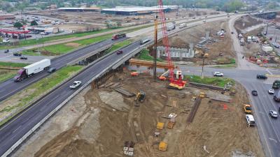
Rock Hill, S.C.’s, Catawba River Bridge on U.S. Highway 21 has served communities in the area well for more than 65 years. But this span over the Catawba, though it’s been a benefit to generations of motorists, also had outlived its usefulness. It has been found to be structurally deficient and functionally obsolete based on inspection criteria, according to David Rister, interim bridge construction engineer with South Carolina Department of Transportation (SCDOT).
The existing bridge is a two-lane structure which is being replaced with a five-lane structure. The new bridge is 1,000 ft. (305 m) in length and the existing structure is 970 ft. (295 m) long. The new structure will have bike lanes and wide, safe sidewalks for pedestrians — unlike the older bridge. This is a sizable project, according to Rister.
Though there was a clear need for a new, more reliable structure at this location, what was definitely unclear was exactly how best to proceed with the construction of a new bridge. This stretch of the Catawba River is quite shallow in parts, according to Troy Carter, REA Contracting project manager.
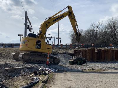
“One side is extremely shallow,” said Carter. “During the autumn, a barge could be in between floating and not floating; some days you can float equipment and some days you can’t. The riverbed rock also is very hard. The drilling contractor was able to cut through the rock with their rock core barrel and excavate down into the rock, proceeding at one foot an hour or less.
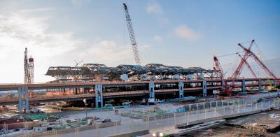
“Early on in the project we installed drill tap casings and the columns rising up out of the water. Doing that work required floating barges and dealing with the permitting issues involved with the Army Corps of Engineers; those were among the major challenges on the job. The next phase of the project involved the installation of the bridge’s eleven 60-ton girders which would span the river. This work would be problematic using barge-mounted cranes. As a result, we searched for some alternate method of placing girders on the job.”
The new span required eleven girders to be put in place; some needed to be placed nearly 100 ft. (30.5 m) away from the existing bridge. There were basically two options for lifting each of the girders: the first involved lifting the beams off the existing bridge and moving them into place by crane and the second was to come up with some crane-less, in-place system using the existing bridge structure completely.
With the first method, using cranes to position the girders, at some point it becomes impossible to reach the position where the girder needs to be and the beam will to have be set down before a crane picks it back up to move it around again. But moving cranes around with such a shallow, rocky bed on the river is a risky proposition, according to Carter.
Also, with the river at this point, there is no way to block the entire river without receiving a variance from the Army Corps of Engineers.
“With this river being only partially floatable for the barges and unable to float on the side where rocks are just below the surface, that pointed us in the direction of finding a safer situation for performing this work,” said Carter.
“If we float a barge down and it’s not perfectly level or just out of level — there is only a small amount allowable for it to be out of level — that puts you in a tricky situation with your cranes. If you aren’t sure if your barges are floating, but instead are sitting on the bottom of the riverbed, it can make the lifting of girders by the cranes problematic. We could have used cranes in that situation. But they would have been a pair of massive 150-ton plus sized cranes to move the girders into place.
“The second system — the one we ended up using — was much safer overall,” Carter explained. “We haven’t done anything like this before; I’m not at liberty to discuss the cost savings, but the increased safety using this method clearly makes this a much better fit.”
The present job does have two cranes, a 100-ton (90 t) crane and a 50-ton (45 t) crane at the bottom of the work site. One of these is situated on the side of the river that they use to move frames to the next position. The other is on the opposite shore. These are much lighter cranes than those that would have been used if the beams were lifted using cranes on river barges.
REA Contracting had to receive permission from the dam upstream, owned by Duke Power. Duke Power operates the water control level in Lake Wylie as they generate power. They also regulate the height of the water in the lake. In order for REA Contracting to move its barges it had to get Duke Power to open up a couple of gates in order to get enough water in the Catawba River so that the barges would float.
Construction superintendent on the job, Emilio Valentin, is skilled in computer graphics, something he enjoys in his spare time. The talent he’s developed has come in handy with the sketch program that helped him assemble a detailed graphic series of steps for a presentation explaining how the bridge is being assembled for the power company so that it would understand why its help was needed with the controlled release of water upstream. Valentin also has encouraged his work crews both to use the computer to understand how the system is put together and to offer their advice and suggestions for streamlining the construction process, which they’ve done on occasion.
“Impetus for assembling that presentation came when we had to give the power company a clear explanation and justification of why we needed them to open the gates,” said Carter. “They didn’t just do it, but needed to know why and we stayed in close contact with them. Emilio did a great job of pulling all of that together. I really have to give him credit for the PowerPoint production he constructed.”
On one of the fall nights that U.S. 21 was shut down and traffic detoured to the nearby interstate, three semis on the north side of the river awaited word to proceed onto the bridge. When a truck received the signal, it pulled forward to the place where four crews of workers in work platforms on each side of the framework in place prepared to lift the beam off the truck’s trailer. Chain hoists were strapped onto steel loops embedded in the concrete at the two ends of the beam. The chains rattled through a system of chain winches as they slowly pulled the beam up and then over to place on the span where they were to be situated.
The chain hoists were operated through both hand power and the running of small handheld drills spinning the long strands through the winches. Once the beam was moved into place above where it is to be lowered, the chains were again run through the winches in reverse. The beam then slowly but surely reached its final destination.
The process was noisy but amazingly quick and fairly effortless aside from a great deal of chain movement by those in the work platforms. At one point a chain snagged in the chain-winch equipment. Lubricant sprayed generously on the chain links quickly remedied the situation and work continued. When the last truck pulled away and the beam was in place parallel to all the others, work for the night was done. All this lifting of the huge bridge beam components was done without a single crane in sight.
Though there are smaller cranes in each bank of the Catawba River, they have limited access to much of the work being done out over the main body of the river. The one frame used for placing the girders during construction always rolls forward on top of the girders that are already set until it eventually reaches land. Once on land, REA Contracting can use one of its cranes and assist with the girder erection, according to Valentin.
A combination of one crane and one frame is used to set girders over land said Valentin.
“The crane picks up the girder on one end while the frame picks up on the opposite end, as the crane travels with the girder attached, the frame trolley system follows keeping the girder parallel until the girder reaches the final location to be lowered.
The frame has a barrier wall with counter weights sitting on it to keep it upright as it travels forward on the girders. Once work crews get to a point where they can move ahead, the bottom brackets are loosened and the whole thing rolls on the beams that they’ve set. It’s designed to actually roll on the beam; the whole framework stays together on the beam and then they pull it ahead with cables.
“We wanted to use a system where there was no chance of an accident on the river bottom,” said Valentin. “We had to go ahead and be self-sufficient in the absence of no big equipment. Instead of huge equipment we went with the use of small come-alongs just to get things into position. With such a span as this, it is difficult to reach and maneuver things with cranes from one side to the other.”
Cable-winches allow things to be pulled ahead in increments. Relatively small winches were used.
“We are moving around something that’s fairly heavy with a system which doesn’t take much to set it in motion,” added Valentin. “This one-half section in theory takes 3,000 pounds of pull to move it forward. You don’t need much to pull it. But we always put a little bit more in there just in case one come-along fails while you’re pulling, so you’re not stuck. Once that frame gets into position, then there is a piece on the bottom that we’ve got to tie up and secure the lifting equipment to.”
Back on the ground below, a John Deere 225 track hoe mounted atop a barge maneuvered the barge by scratching on the bottom to pull itself around. When the equipment was in place, a man-lift was set up to assist on securing the lifting frame to the bridge substructure. A Manitowoc M-222 crane is on one side of the river for handling 100-ton (91 t) loads. On the other side an M-150 works on the south side of the river handling up to 50-ton (45 t) loads. An LS-108 crane works up on top of the bridge.
Coastal Casson was the bridge foundation contractor on the project. Performance Management Contracting, (PMC) is the grading contractor.
The project is part of the normal 80-20 federal process involving bridge replacement dollars and the bid tab on this job is approximately $16,000,000; there were eleven bidders on the project. The job started in July of 2010 and the project is slated to be completed by the end of 2012.
The bridge construction work has not really been affected by the overnight showers that have been prevalent in the area for the early months of fall 2011; however, the required grading work has been affected a bit more due to wet weather.
“We tend to be able to work as long as the sun is out. But if the girders are wet, we don’t work,” added Carter. “That’s a risk we don’t want to take.”
Construction Equipment Guide
470 Maryland Drive
Fort Washington, PA 19034
800-523-2200
Construction Equipment Guide covers the nation with its four regional newspapers, offering construction and industry news and information along with new and used construction equipment for sale from dealers in your area. Now we extend those services and information to the internet. Making it as easy as possible to find the news and equipment that you need and want.
Contents Copyrighted 2024, by Construction Equipment Guide, which is a Registered Trademark, registered in the U.S. Patent Office. Registration number 0957323. All rights reserved, nothing may be reprinted or reproduced (including framing) in whole or part without written permission from the publisher. All editorial material, photographs, drawings, letters, and other material will be treated as unconditionally assigned for publication and copyright purposes and are subject to Construction Equipment Guide’s unrestricted right to edit and comment editorially. Contributor articles do not necessarily reflect the policy or opinions of this publication.
Read our privacy policy here.
Mastodon