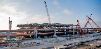
The Ontario, Canada, Power Authority (OPA) entered into an agreement for the construction of a new 1,005-megawatt natural gas-fired power plant. Greenfield Energy Centre L.P., a partnership between Calpine Corp. and Mitsui & Co. Ltd., owns the plant, which is located in Courtright, St. Clair Township, near Sarnia, Ontario.
Sandwell Engineering of Vancouver, British Columbia, oversaw the co-generation plant’s construction. Goodfellow Construction of Corunna, Ontario, the project’s subcontractor, installed a high-pressure water pipe for the turbine cooling system, a part of a complicated closed-loop system.
The water cools the gas-powered turbines and is transmitted from a pump pit to branch pipes, located outside of the cooling tower’s main structure. When the water hits the “T-Pipe,” it is diverted north and south along a tapered main pipe.
The pipe has a series of discharge leads at intervals along the pipe. The discharge leads then transport the water directly to the top of the cooling tower toward a series of turbines.
Tight Quarters Require Alternative to Tight Sheeting
The project challenged contractors because the main pressure pipeline outside the structure was installed 12 to 14 ft. (3.7 to 4.3 m) deep and only 1.5 ft. (.5 m) from the cooling tower’s concrete foundation. This made shoring or shielding the pipeline trench difficult because the walls of the trench needed to be cut vertical and still maintain the stability of the adjacent soil. Consequently, some type of trench shielding system was needed that would fit within the 1.5-ft. space.
Contractors opted not to use traditional tight sheeting due to vibrations possibly destabilizing the soil under the nearby structure foundation.
Contractor Seeks Out Trench Shielding, Shoring Manufacturer
Needing a custom shoring solution, Goodfellow contacted Efficiency Production Inc., a U.S. manufacturer of trench shielding and shoring.
“Someone had told me of the concept of Slide Rail and when I did an Internet search, I landed on Efficiency’s Web site,” Randy McKenney, field coordinator of Goodfellow Construction, said.
“After calling Efficiency, I talked at length with Greg Ross [Efficiency’s slide rail installer and sales manager] and he sent me initial information, manuals, videos, and a proposal drawing; really everything I needed to bid on the project,” McKenney added. “Greg even came out to the job site to look at the conditions. We were competing for the job against one other contractor who came in with no other shoring options other than open-cut, so I think the Slide Rail option helped us land the job.”
’Dig and Push’ System Fits the Bill
Efficiency’s universal slide rail is a component shoring system comprised of steel panels (similar to trench shield sidewalls) and vertical steel posts. The system can be used in a variety of configurations, such as small four-sided pits; large unobstructed working pits of infinite size with Efficiency’s ClearSpan System; or in a linear Multi-Bay configuration to install length of pipe as long as 40 ft. (12 m).
The slide rail can be installed simultaneously during trench or pit excavation by sliding panels into integrated rails on the posts — either double or triple rails depending on needed depth — then pushing the panels and posts incrementally down to grade as the pit is dug. This process commonly is referred to as a “dig and push” system.
Slide Rail Prevents Two-Month Delay
The first step for Goodfellow was to install 120 ft. (36.6 m) of 96 in. (228.6 cm) diameter cement-lined steel pipe starting from the pump pit to “outside” the cooling tower. This section of pipe was installed before the tower’s foundation was begun, and Goodfellow elected to open cut and slope the trench. That first 120 ft. ended at a T-vault, which is just outside where the cement foundation of the building was to be laid by Hayman Construction Works, a cement company with whom Goodfellow was working as a joint venture.
As soon as construction began on the foundation open-cutting was no longer an option for the north and south branch-pipeline trenches.
“They wanted to start that foundation on time, and if it were not for Slide Rail, the whole project would have been held up for at least two months while we installed the pipe branches,” McKenney said.
Slide rail is installed and removed incrementally, which allows the trench to be properly shored throughout the entire installation or removal process, and always provides ’active shoring,’ maximizing the stability of the surrounding ground, according to the manufacturer. This allowed Goodfellow to install slide rail 6 in. (15.2 cm) from the structure’s foundation.
McKenney added that, “The slide rail system worked very well and was very consistent, which was critical as the pipe needed to go in exactly perpendicular to the outside of the tower structure. Using Slide Rail for the first time there was a learning curve, but with Greg’s installation assistance, my crew picked it up fairly easily.”
Goodfellow installed first the south branch pipeline 375 ft. (114 m) from the center T-foundation. Each bell-spigot joint of pipe is 20 ft. (6 m) long and is welded inside with a cement diaper over the outside joint. An 8-ft. (2.4 m) diameter pipe then was installed near the T-Vault and tapered to 6 ft. (1.8 m) diameter pipe at the end of the pipeline to maintain constant pressure. Ten of the pipe sticks, including the T-vault, had prefabricated 3 ft. (.9 m) diameter chimneys, which were installed at intervals on the pipeline for transmitting the water to the top of the tower.
Once the south branch was completely installed, backfilled, and the slide rail components removed, Goodfellow began installing the north branch in the same manner. The total pipeline outside the tower was 750 ft. (228.6 m).
Goodfellow rented a seven-bay linear application slide rail system factory-direct from Efficiency Production. The bays were 20 and 14 ft. (6 and 4.27 m) long and the linear posts 24 ft. (7.3 m) tall. Goodfellow used 10 ft. (3 m) spreader pipes on the 1 ft. (.3 m) wide by 7 ft. (2.1 m) tall parallel beams for a total trench width of 12 ft. (3.7 m). The trench was excavated in Type-C, sandy-clay soils.
The new power plant is scheduled to open February 2008. Greenfield Energy anticipated that the project would create up to 800 jobs during the construction period and approximately 25 to 30 full-time permanent jobs during facility operations. The Greenfield Energy Centre was selected for development through the Ontario Ministry of Energy’s 2004 open and competitive request for proposal (RFP) process for new, clean energy.
Efficiency Production, Inc.’s standard and custom trench shielding and shoring systems are professional engineer certified to meet OSHA and MIOSHA standards.
(James McRay is the marketing and media manager of Efficiency Production Inc.)
Today's top stories


