List Your Equipment  /  Dealer Login

St. Paul Sewage Lift Station

Tue January 05, 2010 - Midwest Edition
Dorinda Anderson


What should have been a fairly routine sewage lift station installation, turned out to be a much larger project when overly wet soil was encountered.

The project is located just east of downtown St. Paul, Minn., and a quarter of a mile away from the Mississippi River on Highway 61 and Lower Afton Road. The sewage lift station is located at the bottom of a river bluff so everything drains to that point, explained Glen Haugen, of Kober Excavating of St. Paul, Minn.

Originally it was planned that a 36-sq.-ft. (3.3 sq m) box would be sufficient to shore the area, but because of the soggy soil, Metropolitan Council wanted an additional depth of rock to support the structure. The end design became a 45 by 45 by 24 ft. (13.7 by 13.7 by 7.3 m) high clear span slide rail system. This design required the use of double cross brace roller assemblies within the system to ensure the box was stabilized. The project became much more intensive with the oversized box and the additional site specific engineering that went with it, Haugen said.

“There were no indications showing the soil would be that bad.”

The Metropolitan Council’s decision to use an additional 5 ft. (1.5 m) of rock and fabric under the foundation made the excavation significantly larger and deeper in order to accommodate the additional size of ground support, said Gary Carlson, owner of Gary Carlson Equipment, supplier of the Pro-Tec Slide Rail shoring system used on this project.

“We were able to reconfigure the shoring pieces from 16-foot panels to the larger double sets of 20-foot long panels,” Carlson said.

Kober Excavating dug a sub cut around the whole area and installation of the double cross brace pit began. Approximately 23 ft. (7 m) of vertical panel height was utilized to get down safely in this mucky ground. The basic placement was done in just a couple of days, but at that point some additional dewatering had to be done because ground water was coming up, Carlson said.

Additional dewatering equipment was moved in and used for a couple of days until the soil was dry enough to continue pushing the system down so the concrete placement of the structure could be done, Carlson added.

“We had a lot of groundwater and dewatering conditions to deal with,” Haugen explained. “It created a challenge throughout the whole project.”

A dewatering system ran the entire length of the project.

“We had to use rock and pumps inside the slide rail because the well points were not removing the water as we would have liked it to,” Haugen said. “The material at the site is silty clay that holds water. We had ground water coming in for at least the last 15 feet we had to go down.”

The Pro-Tec Slide Rail shoring product made it all possible, Haugen said.

“It was a rather big project to get in the ground but everything went well.”

This project was definitely not routine, Haugen said.

“Normally we don’t have to dig quite this wide, but the site conditions required the 5-feet of rock and the Pro-Tec shoring product for stability.

Mike Doyle of Gary Carlson Equipment said, “Once the system and the rock were in place, the concrete work could begin.”

After the 3 ft. (1 m) thick base slab cured the forms were stripped and the spreader posts were braced at four points off of the slab.

“We were then able to pull the double cross brace sets up and install the waler beams around the perimeter. Once the waler installation was completed we then removed the cross braces to create a 45 square-foot clear span system in the ground,” Doyle said.

The concrete walls were poured in one pour, requiring about 800 cu. yds. (611 cu m). The walls of the structure were 2 ft. (.6 m) thick and are 27 ft. (8.2 m) tall when measuring from the top of bottom slab. Inside the area is a wet well with submersible pumps in order for the lift station to handle additional water.

There is an existing 48-in. (121 cm) storm sewer within 15 ft. (4.5 m) of the new lift station and excavation wouldn’t have been possible without the Slide Rail system, Haugen said.

The old existing lift station was continually used during the construction process, which included first installing some 90-in. (228 cm) pipe that was brought up to the lift station. Material had to be lifted on top of that, which required extra work just because of the lack of space, he added. Pipe installation went well.

The lift station was poured in place by Kelleher Contracting, of St. Paul.

“The entire 26-foot structure was done in just one pour, which is why the clear span pit was required,” Haugen explained.

Excavation was done using a Komatsu 750 backhoe and a Komatsu 200 backhoe, along with a loader, a dozer and a compacter. Since none of the excavation materials were hauled off site, everything was stockpiled next to the project, Haugen explained.

Even with the engineering changes that delayed the start the project is still within the time frame for the job, Haugen said.

“I believe the additional engineering and the process to get box approved took additional time and set us back a little, but we’re still within the time frame of the project.”

The project is to be completed next spring 2010. The project was started in June of 2009, though it was originally scheduled to start in March.


Today's top stories

Blalock Crews Build TDOT's $67M Newport Bypass

New Bridges Part of Iowa's $114M Madison Avenue Project

Eagle Bridge Co. Works On Final Leg of U.S. 35 Upgrade

SAKAI Achieves Record Sales, Production

Takeuchi Recognizes Top Dealers at 2024 Dealer Summit

Equip Expo's Summer Giveaway Offers a Chance for Lifetime Trade Show Registration, Gift Card, Hotel Stay

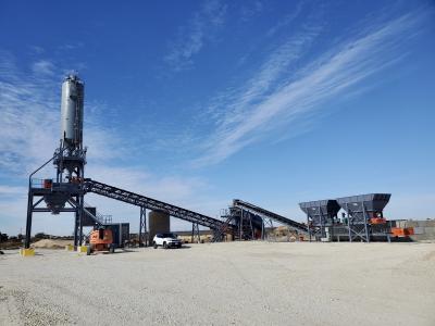
Tennessee's Pugmill Systems LLC Expands Its Product Offerings to Include Concrete Plants

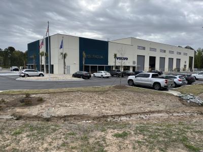
ASCENDUM Machinery Opens New Savannah, Ga., Facility


aggregateequipmentguide-logo agriculturalequipmentguide-logo craneequipmentguide-logo forestryequipmentguide-logo truckandtrailerguide-logo
39.96250 \\ -83.00610 \\ Columbus \\ PA