


The mighty Mississippi River requires mighty-strong manmade structures to corral it and to withstand the volume and pressure of water exerted upon them. It follows that the simple addition and lengthening of a lock for faster handling of river vessels is a mighty undertaking, a multi-year, multi-million-dollar one.
Lock 25 near Winfield, Mo., is one of seven new locks authorized by Congress to be built on the upper Mississippi. The project formally began in May 2024 with some preparatory work on and around the existing lock, but completion is years away — with letting of primary construction contracts not happening till 2027 and construction expected to take eight years.
Most of the undertaking is, in fact, still in the design stage, according to Bryan Dirks, the project's lead engineer. Dirks works for the U.S. Army Corps of Engineer's Inland Navigation Design Center in the St. Louis District.
"We have been designing the lock for a couple of years now," he said. "It is an important project for the nation, a massive project and a complex one."
The upper portion of the Mississippi River — that is, some 240 mi. of it from Minneapolis, Minn., to Winfield — drops about 400 ft. in elevation. The topography is such that a constant depth of water does not naturally occur. The natural river, in fact, ranges from less than 2 ft. deep to nearly 200 ft. deep.
So that vessels could be assured of a navigable channel at least 9 ft. in depth the length of the river, the Corps in the 1930s built a series of dams and locks on the upper Mississippi. Each of the 27 dams effectively created a pool upstream clear to the base of the dam above it. The lower portion of the river doesn't require locks because other rivers join the Mississippi in that region to enhance the river's depth all the way to the Gulf of Mexico.
While dams on the river create pooling, they also stymie the passage of vessels. To allow river traffic, the 1930s engineers built a lock next to each dam. A lock is an enclosed channel in which the level of water can be raised and lowered. Vessels traveling downstream enter a lock and the water in it is lowered, dropping the vessel to the downstream level of the river below the dam. Boats and barges moving upstream are similarly transferred to the higher level on the other side of the lock.
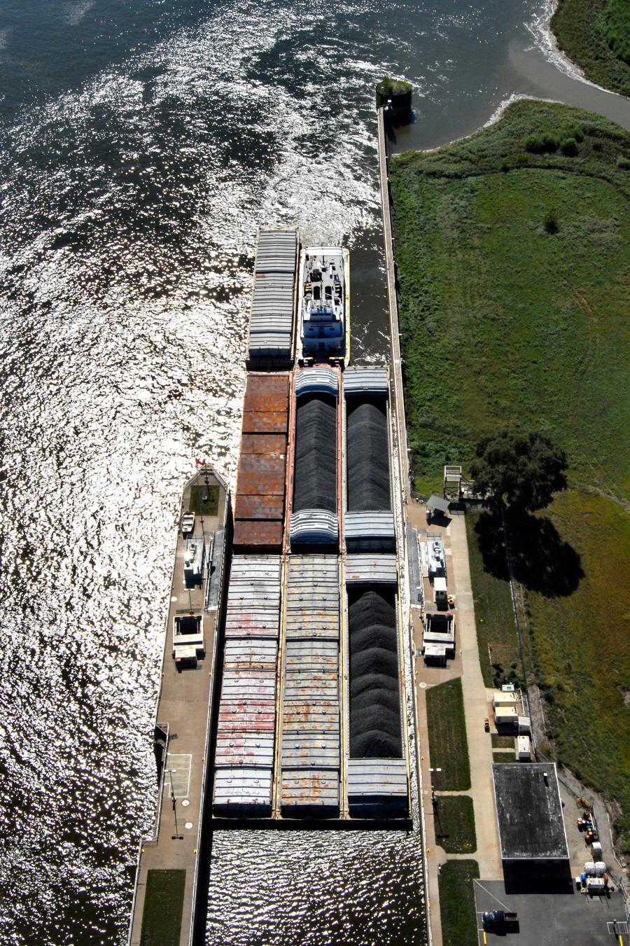
The reason for constructing new locks is to speed the passage of barges. Typically, barges today are yoked in groups of 15, an assembly that exceeds the 600-ft. length of existing locks. Consequently, to pass through the locks, the group of barges must be split in half, with the tug or towboat moving them though the lock in two trips. The new locks will be 1,200 ft. long and able to let an entire string of barges through in one lockage.
The 85-year-old existing lock at Winfield will be kept functioning to handle pleasure craft and other smaller vessels and will function as a redundant chamber when the main lock is down for maintenance. It also will become part of the new construction.
The old lock's wall nearest the Missouri shoreline will remain as is. However, its outer wall will separate the river water in one lock from water in the adjoining lock, so it will serve both locks. To be able to do so, the wall needs to be modified and strengthened, some of which was accomplished in the earliest phase of the project work.
That wall — called the intermediate wall — also will be lengthened 600 ft. to form one side of the new 1,200-ft.-long lock. Then a third wall — the farthest one into the river and nearest one to the Illinois shoreline on the other side of the Mississippi — will be wholly constructed to match the now-1,200-ft.-long intermediate wall. Thus, two locks will be in place, one 600 ft. long, the other twice that length, both sharing a common intermediate wall.
To describe the physical relationship of the two locks is easy enough. To modify and build the lock walls is something else — and to construct the walls and gate systems in moving water with fluctuating currents and against powerful hydraulic pressures is a genuine challenge.
Case in point: The water right below the dam spillway and adjacent to the new lock wall will be especially turbulent.
"The moving water does complicate things when constructing in a river. The river wall starts downstream next to the flow from the dam gates and that flow will make it more difficult for construction," Dirks said.
To shield the working area from the worst of the turbulence, a temporary separator wall will be erected to reduce the velocity.
"Farther downstream, flows become less turbulent, and velocities slow down."
Lock walls are not cinderblock and mortar creations such as the wall separating a backyard from an alley. These are massive structures. Dirks refers to an individual wall section as a "monolith." Each section (or monolith) is 30 ft. by 30 ft. — that is, the wall is 30 ft. thick — by 40 ft. high. Inside its steel panels is poured concrete, lots of concrete. The volume of concrete utilized in the project is equivalent to that in 50 Olympic-size swimming pools, according to the engineer. The steel paneling is removed once the concrete hardens.
Each huge wall section will be anchored to the bedrock under the river by four 48-in. in diameter steel drilled shafts vibrated into place. Rebar and concrete will then fill the shafts and the section of wall built around and upon them. Some sheet pilings also will be driven into the riverbed. The bottom part of the wall will be poured in place using box forms filled with "underwater concrete," or tremie concrete, and then the forms are pumped dry.
The wall sections will be seamlessly united, water-tight, that is. The ability to completely dewater a lock is important so that maintenance crews can work in the chamber. The bulkheads at either end also will be designed not to leak river water into the lock. However, because they are movable panels, instead of fixed-in-place walls, some minimal leakage is expected during maintenance periods.
Running through each outer concrete wall section is a 14-ft.-in-diameter culvert, or pipe. When the wall sections are seamlessly united, the culvert sections will be joined to become one and run the length of the wall. This culvert is the means of flooding the lock as well as emptying it. A valve is opened for an intake port upstream, and gravity will flow the water into the culvert and, from there, into the lock. To lower the level inside the lock, another valve is opened, and the water will rush out into the culvert and eventually join the river in a discharge port downstream.
"It is a pretty simple process," Dirks said, "but doing it safely is important."
Dirks added that a scale model of the lock was built and tested to make sure the incoming water doesn't "rock the boat" and cause damage to barges inside the lock wall. Tolerances inside the lock are, after all, fairly small: The new lock will be 110 ft. wide, and a string of grouped barges is 105 ft. wide.
Two other walls will be constructed in the river, one upstream of the lock, the other downstream. The upper wall will be 1,200 ft. long and will allow the towboat operator to use it as a guide to align the tow prior to entering the lock. The lower wall will be half as long and help the operator of the departing vessel or barges safely re-enter the river channel.
As with the lock walls, both guard walls will be founded on bedrock using the drilled shafts. How many shafts are we talking about? In the two guard walls, 144 shafts will be positioned. In the lock walls containing the culvert, 270 of the shafts will be fixed in place. Of course, all this shaft work and eventual installation of the monolithic wall will be done working from barges floating on the river.
The riverbed is sand, with some identified riprap — irregular rock — identified in the area of the new lock. That rock will be removed in a future stage of the project. Some dredging of sand will have to be done on the downstream end of the lock and some sand added to the upper end to level out the bottom.
Dirks has been with the Corps for 15 years, working on a variety of projects. For the next decade or more, Lock 25 will be his principal, if not sole, focus. Major parts of the work have yet to begin, but the preliminary work by long-time Kansas City civil and marine construction firm Massmann Construction was a success.
Other ongoing work as the project begins to gain momentum includes fabrication of the lock bulkheads, construction of some support buildings on site for Corps and contractor use, and establishment of a concrete quality assurance lab for all that concrete going into the lock walls. On site and on the water will be some heavy-duty cranes, long-reach excavators, concrete delivery trucks, box forms, piledrivers, shaft vibrators and assorted other machinery.
"We try to stay out of the means and methods of contractors and of the equipment they use," Dirks said. "But there will be a whole lot of work from barges."
Once begun, the offshore and onshore work is anticipated to be year-round. However, this being the Midwest, weather events such as big freezes, or heavy rains that raise the level of the river, might interrupt the contracted work. It is hoped that river traffic will continue to be able to pass through the existing lock, at least most of the time.
"Traffic on the river has accelerated since 1939 when the nine-foot channel was created," said Dirks. "That means that they didn't have the amount of river traffic to contend with that we have today."
He expects there will be some short-term closures.
"We're working with partners to define what they will look like."
Lock construction technology has changed "quite a bit" since 1939, of course, including the machinery and materials utilized. For example, Dirks noted that the existing lock is built on timber pilings — "there's a sea of timber piles under the existing lock and they don't go down to bedrock" — and cranes are bigger.
Dirks acknowledges that the ability of the Corps and contractors to construct the numerous locks in a relatively short period of time was impressive, However, safety requirements are more stringent now than they were in 1939 — for good reason. That is expected to impact the pace of work, as well.
"All construction work has risk. We are requiring contractors to have robust safety programs," he said. CEG


