After three years, major improvements to the Birmingham Water Works’ century-old Shades Mountain Filter Plant in Birmingham, Ala., are now complete. In August 2009, general contractor B.L. Harbert International LLC (BLHI), began work on the facility, which is located off Highway 280 just three miles south of downtown. Construction on the $41 million project was finished in June 2012.
Jeremy Pipkin, LEED AP with BLHI explained, “The plant needed to increase its storage capacity and upgrade its existing pumping system to comply with updated state and federal regulations. It varied throughout the duration of construction, but the maximum number of personnel on site was around 125 at one time.”
Pipkin said the objective of the Phase II upgrade project at the plant is to increase the water storage capacity of the plant by 600 percent, while consolidating pumping operations and upgrading electrical systems for the entire plant. This will add two six-million-gallon pre-stressed concrete clearwells, a transfer pump station, a finished water pump station, a new electrical building and a new lime treatment facility. A total of 16 horizontal split case pumps and three vertical turbine pumps will be added to the plant, which will replace the plant’s older pumps that are spread throughout the campus.
The project also adds approximately 7,000 linear ft. (2,133 m) of large diameter ductile iron pipe ranging from 24 to 60 in. (61 to 152 cm) in diameter. This new pipe ties into the existing lines of the system in 19 different tie-in locations. A majority of the existing lines are between 50 and 100 years old and require tie-in with custom fittings to tie ductile iron pipe to cast iron lines and concrete cylinder pipe with no existing means to stop the current flow. Different methods are utilized to temporarily stop the flow to allow the tie-ins to occur. In some cases line stops were utilized to facilitate this and in other cases divers were sent into the existing operating clearwell to plug the lines exiting the clearwell.
“The biggest challenge was working around the existing piping and structures of the 100-plus-year-old facility,” said Pipkin. “We had to make certain to protect existing piping while installing the new 28-ft. deep transfer pump station. We were also tying in to several existing pipes in the system where flow needed to be stopped prior to the tie-in work commencing. We accomplished stopping flow by utilizing line stops in some cases. In other cases we put divers in the existing clearwell to perform camera observation of the lines. After we observed the lines we knew which ones to plug to stop flow. We also had to make certain that our actions onsite did not affect the distribution service since the system for the city relies on several different filter and pump stations to balance the supply of water to customers.”
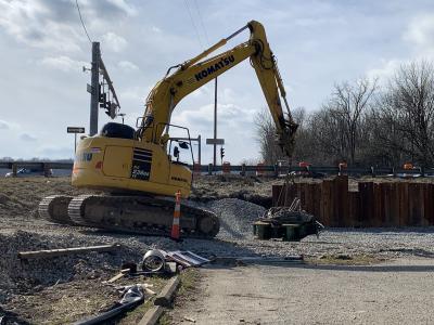
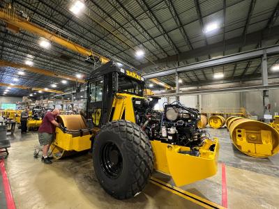
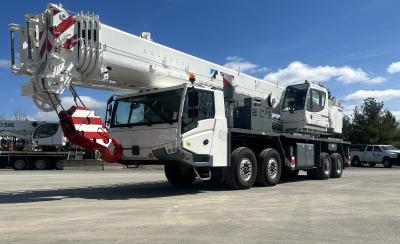
Pipkin continued, “We used equipment from mini-excavators to D-10 dozers and literally everything in between to clear and excavate the land. We utilized trackhoes (PC-400’s), D-5 dozers, and sheepsfoot compactors to install the piping. We also used specialized line stopping equipment to stop flow to the lines as well as trench boxes to perform safe excavations. The topography of the site did not allow for access to all areas so a 100-ton Link-Belt crawler crane was utilized for setting formwork and roof trusses. Approximately 5,700 cubic yards of concrete and 7,000 linear feet of large diameter ductile iron pipe also were used.”
Weather did not play a significant role, but crews did encounter a large amount of rock that made excavation more challenging at times. Pipkin said the most time- consuming task was the main line tie-ins, because of the investigative and exploratory time needed to mitigate potential risk exposures. The new additions will not drastically change the way the plant currently functions, but it will ensure that the owner meets or exceeds the latest state and federal regulations as well as providing reliable pumping operations to serve customers for several years to come.
According to Project Engineer Brandon Lawhern of Gainesville, Fla.-based The Crom Corporation, “Crom was the designer and constructor of the prestressed concrete tanks and its accessories in their entirety. This in detail was two 6.0 MG Prestressed Concrete Clearwells with internal circular baffle walls.
“We were required to cast two 185-ft. (56 m) diameter slabs 6-in. (15 cm) thick and constructed two sets of five ring baffles using shotcrete, a pneumatically applied concrete. Then we set a steel diaphragm shell for the exterior tank wall and applied shotcrete to the inside and exterior surface of this diaphragm shell. We then cast two free-span (not column supported) concrete domes. Once this was completed, we prestressed the entire tanks, which causes the tank to remain in constant compression and supports the concrete domes. A thin layer of shotcrete is applied to the exterior surface of the tank wall to protect the prestressing wires wrapped around the tanks. Finally, we painted the exterior of the tanks to get them to final form.”
Lawhern added, “Concrete work is highly dependent on favorable weather, and the weather through the winter served many challenges in an effort to complete the work on schedule.
“More than 6,000 cubic yards of concrete was used to construct the tanks which is more than 410 concrete trucks, along with a crane to move shoring and miscellaneous items, a prestressing rig to pull the prestressing wire at 3,000 PSI around the tank. There was more than 24 miles of wrapping of the tanks with this wire, along with multiple loaders, large air compressors and special equipment.”
Materials included 231.4 tons (209 t) of reinforcement steel, 68.4 tons (62 t) of prestress wire — not including bolsters and 1,370 gallons of paint. As much as 2,066 cu. yds. (1,579 cu m) of concrete was needed for the floor, 878 cu. yds. (671 cu m) for the dome and 3,586 cu. yds. (2,741 cu m) for grout.
“The job lasted from May 2010 through July 2011. Crom’s primary directive is to provide a low-maintenance, long-term design and approach to water storage so that owners are able to keep rates low so that maintenance issues are not a large factor in the service they provide to their clients.”
Other subcontractors on the project included Furmanite, which was responsible for the linestops, and Stone and Sons Electrical. Stone and Sons, which specializes in water, wastewater and industrial projects, assisted the owner, engineer, general contractor, plant management and various vendors in dealing with equipment layouts, process equipment integration and project scheduling. It also coordinated with the power company for the double feed to the plant. Work began in September of 2009 and finished in July 2012
“Our scope for this project was large and complicated,” explained Project Manager Danny Baker. “There was the typical furnish and install of all electrical equipment, raceways, and wiring consisting of medium voltage, 600 volt and low voltage, but we also furnished and installed all instrumentation including, but not limited to, transmitters, gauges, switches and flow meters and related items. We provided new medium voltage substations, wiring and terminations, installed new SCADA equipment complete with the fiber optic backbone for the communication to the plants existing system and integration of the two SCADA systems. Additionally, the security fencing and mow strip was included in our scope, as well as furnishing the raceway and poles for the security and site surveillance.
“One of the biggest challenges was to keep the existing power system for the plant online while the new system was installed and tested, Baker continued. “The systems had to be paralleled so we could change over all existing building feeders and process equipment to the new system and have each maintain the capability of the backup power. There was no margin for error in that any issues could have resulted in plant interruption and BWWB customers not receiving water service.”
The Birmingham Water Works Board (BWWB) oversees one of the top five water systems in the nation, and is the largest water utility in the state, serving more than 600,000 customers in Jefferson, Shelby, Blount, St. Clair and Walker Counties. The filter plant Phase Two project is being implemented to comply with Alabama Department of Environmental Management regulations. Considered a major capital improvement project that involves new piping, electrical upgrades and a new transfer pump station, it will improve BWWB’s current plant operations.
The upgrade was necessary to comply with the Safe Drinking Water Act by providing additional space for water storage to meet peak water demands. It also reportedly increases reliability of treatment, provides an optimal level of primary disinfection, improves the safety of the facility and makes certain that customers receive a continuous supply of high-quality water.
Today's top stories


